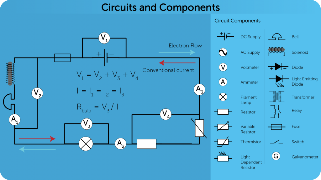
Circuit Diagrams and Components
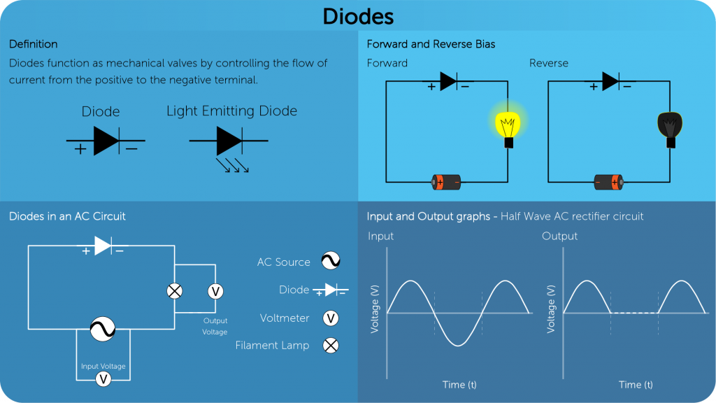
Diodes
Series and Parallel Circuits
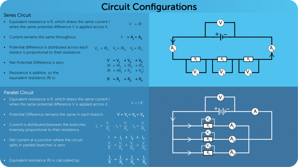
Advantages of connecting resistors in parallel
- Voltage across each resistor = voltage of mains
- Appliance can be switched on and off independently.
- If one appliance goes off, the others stay on.
Potential Divider Circuit
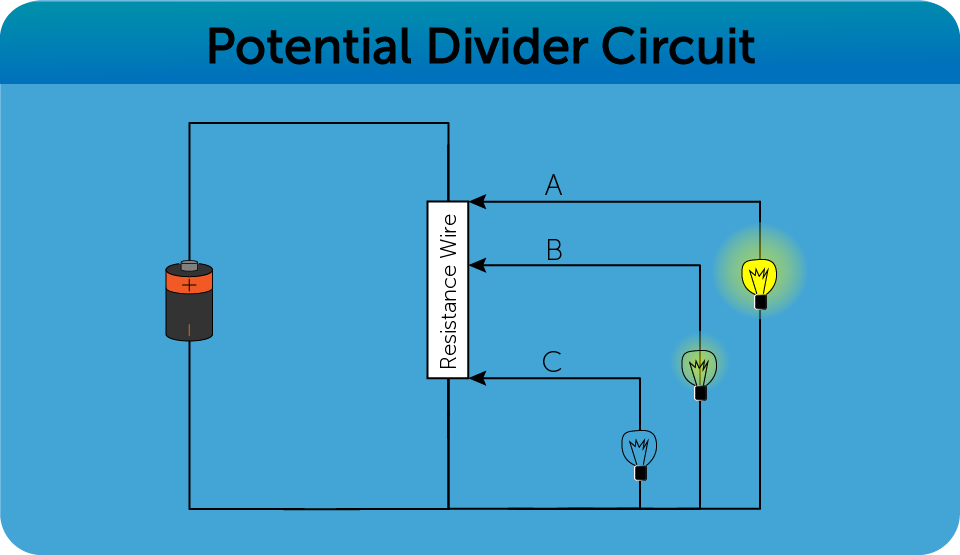
- The potential difference across the resistor is proportional to its resistance.
- In the above example, the bulb and the variable resistance have a maximum resistance of .
- When the slider is at A, the brightness of the bulb will be maximum as the potential difference across it will be maximum.
- The bulb will light at an intermediate brightness when the slider is at B.
- The bulb will not light when the slider is at C as the potential difference across it will be 0.
Relay Circuit
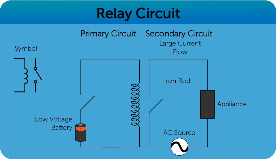
- Works like an electric switch
- It has two coils – primary and secondary.
- A small input current in the primary circuit can be used to turn the switch in the secondary circuit.
- Primarily used for appliances of large loads